Task B. Airport Operations
| Task B. Airport Operations | |
| References | AC 107-2, AC 150/5200-32; AIM; FAA-H-8083-25; FAA-G-8082-22 |
| Objective | To determine that the applicant is knowledgeable in airport operations. |
| Knowledge | The applicant demonstrates understanding of: |
| UA.V.B.K1 | Types of airports such as towered, uncontrolled towered, heliport, and seaplane bases. |
| UA.V.B.K2 | ATC towers, such as ensuring the remote pilot can monitor and interpret ATC communications to improve situational awareness. |
| UA.V.B.K3 | Runway markings and signage. |
| UA.V.B.K4 | Traffic patterns used by manned aircraft pilots. |
| UA.V.B.K5 | Security Identification Display Areas (SIDA). |
| UA.V.B.K6 | Sources for airport data. |
| UA.V.B.K6a | a. Aeronautical charts |
| UA.V.B.K6b | b. Chart Supplements |
| UA.V.B.K7 | Avoiding bird and wildlife hazards and reporting collisions between aircraft and wildlife. |
| UA.V.B.K8 | Airport and seaplane base lighting. |
| Risk Management | [Reserved] |
| Skills | [Not Applicable] |
UA.V.B.K1 Types of airports such as towered, uncontrolled towered, heliport, and seaplane bases (FAA-H-8083-25)
Airport Categories
The definition for airports refers to any area of land or water used or intended for landing or takeoff of aircraft. This includes, within the five categories of airports listed below, special types of facilities including seaplane bases, heliports, and facilities to accommodate tilt rotor aircraft. An airport includes an area used or intended for airport buildings, facilities, as well as rights of way together with the buildings and facilities.
Types of Airports
There are two types of airports—towered and nontowered. These types can be further subdivided to:
• Civil Airports—airports that are open to the general public.
• Military/Federal Government airports—airports operated by the military, National Aeronautics and Space Administration (NASA), or other agencies of the Federal Government.
• Private Airports—airports designated for private or restricted use only, not open to the general public.
Towered Airport
A towered airport has an operating control tower. Air traffic control (ATC) is responsible for providing the safe, orderly, and expeditious flow of air traffic at airports where the type of operations and/or volume of traffic requires such a service. Pilots operating from a towered airport are required to maintain two-way radio communication with ATC and to acknowledge and comply with their instructions. Pilots must advise ATC if they cannot comply with the instructions issued and request amended instructions. A pilot may deviate from an air traffic instruction in an emergency, but must advise ATC of the deviation as soon as possible.
Nontowered Airport
A nontowered airport does not have an operating control tower. Two-way radio communications are not required, although it is a good operating practice for pilots to transmit their intentions on the specified frequency for the benefit of other traffic in the area. The key to communicating at an airport without an operating control tower is selection of the correct common frequency. The acronym CTAF, which stands for Common Traffic Advisory Frequency, is synonymous with this program. A CTAF is a frequency designated for the purpose of carrying out airport advisory practices while operating to or from an airport without an operating control tower. The CTAF may be a Universal Integrated Community (UNICOM), MULTICOM, Flight Service Station (FSS), or tower frequency and is identified in appropriate aeronautical publications. UNICOM is a nongovernment air/ground radio communication station that may provide airport information at public use airports where there is no tower or FSS. On pilot request, UNICOM stations may provide pilots with weather information, wind direction, the recommended runway, or other necessary information. If the UNICOM frequency is designated as the CTAF, it is identified in appropriate aeronautical publications. Figure 14-1 lists recommended communication procedures. More information regarding radio communications is provided later in this chapter.
UA.V.B.K2 ATC towers, such as ensuring the remote pilot can monitor and interpret ATC communications to improve situational awareness (FAA-H-8083-25)
Runway Confusion
Runway confusion is a subset of runway incursions and often results in you unintentionally taking off or landing on a taxiway or wrong runway. Generally, you are unaware of the mistake until after it has occurred. In August 2006, the flight crew of a commercial regional jet was cleared for takeoff on Runway 22 but mistakenly lined up and departed on Runway 26, a much shorter runway. As a result, the aircraft crashed off the end of the runway.
Causal Factors of Runway Confusion
There are three major factors that increase the risk of runway confusion and can lead to a wrong runway departure:
• Airport complexity
• Close proximity of runway thresholds
• Joint use of a runway as a taxiway
Not only can airport complexity contribute to a runway incursion; it can also play a significant role in runway confusion. If you are operating at an unfamiliar airport and need assistance in executing the taxi clearance, do not hesitate to ask ATC for help. Always carry a current airport diagram and trace or highlight your taxi route to the departure runway prior to leaving the ramp.
Another way to mitigate the risk of runway incursions is to write down all taxi instructions as soon as they are received from ATC. [Figure 14-50] It is also helpful to monitor ATC clearances and instructions that are issued to other aircraft. You should be especially vigilant if another aircraft has a similar sounding call sign so there is no mistake about who ATC is contacting or to whom they are giving instructions and clearances.
Read back your complete ATC clearance with your aircraft call sign. This gives ATC the opportunity to clarify any misunderstandings and ensure that instructions were given to the correct aircraft. If, at any time, there is uncertainty about any ATC instructions or clearances, ask ATC to “say again” or ask for progressive taxi instructions.
ATC Instructions
Title 14 of the Code of Federal Regulations (14 CFR) part 91, section 91.123 requires you to follow all ATC clearances and instructions. Request clarification if you are unsure of the clearance or instruction to be followed. If you are unfamiliar with the airport or unsure of a taxi route, ask ATC for a “progressive taxi.” Progressive taxi requires the controller to provide step-by-step taxi instructions.
The final decision to act on ATC’s instruction rests with you. If you cannot safely comply with any of ATC’s instructions, inform them immediately by using the word “UNABLE.” There is nothing wrong with telling a controller that you are unable to safely comply with the clearance.
Using Proper Radio Procedures
Using proper radio phraseology and procedures contribute to a pilot’s ability to operate safely and efficiently in the airspace system. A review of the Pilot/Controller Glossary contained in the AIM assists a pilot in the use and understanding of standard terminology. The AIM also contains many examples of radio communications.
ICAO has adopted a phonetic alphabet that should be used in radio communications. When communicating with ATC, pilots should use this alphabet to identify their aircraft.
UA.V.B.K3 Runway markings and signage (FAA-H-8083-25 Pgs. 14-5 – 14-16)
Runway Markings and Signs
Runway markings vary depending on the type of operations conducted at the airport. A basic VFR runway may only have centerline markings and runway numbers. Refer to Appendix C of this publication for an example of the most common runway markings that are found at airports.
Since aircraft are affected by the wind during takeoffs and landings, runways are laid out according to the local prevailing winds. Runway numbers are in reference to magnetic north. Certain airports have two or even three runways laid out in the same direction. These are referred to as parallel runways and are distinguished by a letter added to the runway number (e.g., runway 36L (left), 36C (center), and 36R (right)).
Runway Safety Area Boundary Sign
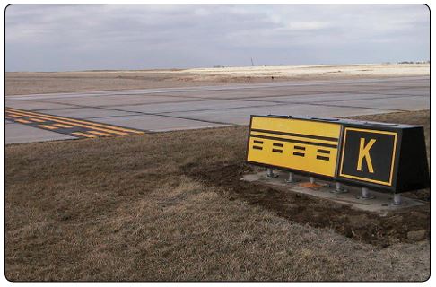
Some taxiway stubs also have a runway safety area boundary sign that faces the runway and is visible to you only when exiting the runway. This sign has a yellow background with black markings and is typically used at towered airports where a controller commonly requests you to report clear of a runway. This sign is intended to provide you with another visual cue that is used as a guide to determine when you are clear of the runway safety boundary area. The sign shown in Figure 14-8 is what you would see when exiting the runway at Taxiway Kilo. You are out of the runway safety area boundary when the entire aircraft passes the sign and the accompanying surface painted marking.
Runway Holding Position Sign
Noncompliance with a runway holding position sign may result in the FAA filing a Pilot Deviation against you. A runway holding position sign is an airport version of a stop sign. It may be seen as a sign and/or its characters painted on the airport pavement. The sign has white characters outlined in black on a red background. It is always collocated with the surface painted holding position markings and is located where taxiways intersect runways. On taxiways that intersect the threshold of the takeoff runway, only the designation of the runway may appear on the sign.
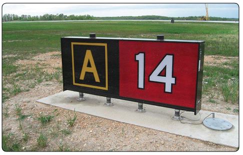
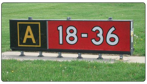
If a taxiway intersects a runway somewhere other than at the threshold, the sign has the designation of the intersecting runway. The runway numbers on the sign are arranged to correspond to the relative location of the respective runway thresholds. Figure below shows “18-36” to indicate the threshold for Runway 18 is to the left and the threshold for Runway 36 is to the right. The sign also indicates that you are located on Taxiway Alpha.
If the runway holding position sign is located on a taxiway at the intersection of two runways, the designations for both runways are shown on the sign along with arrows showing the approximate alignment of each runway. In addition to showing the approximate runway alignment, the arrows indicate the direction(s) to the threshold of the runway whose designation is immediately next to each corresponding arrow.
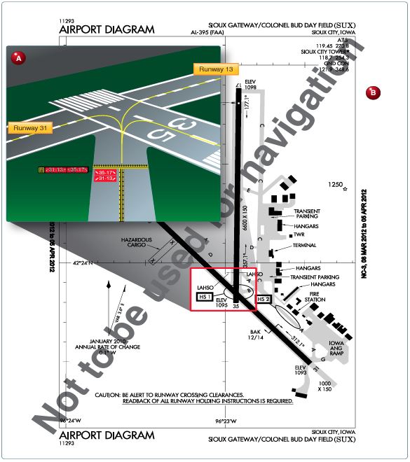
This type of taxiway and runway/runway intersection geometry can be very confusing and create navigational challenges. Extreme caution must be exercised when taxiing onto or crossing this type of intersection. Figures below shows a depiction of a taxiway, runway/runway intersection and is also designated as a “hot spot” on the airport diagram. In the example, Taxiway Bravo intersects with two runways, 31-13 and 35-17, which cross each other.
Surface painted runway holding position signs may also be used to aid you in determining the holding position. These markings consist of white characters on a red background and are painted on the left side of the taxiway centerline. Figure below shows a surface painted runway holding position sign that is the holding point for Runway 32R-14L.
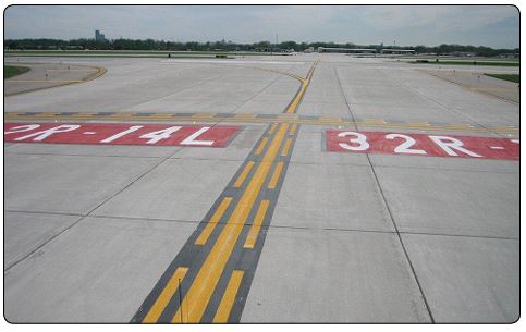
You should never allow any part of your aircraft to cross the runway holding position sign (either a vertical or surface painted sign) without a clearance from ATC. Doing so poses a hazard to yourself and others.
When the tower is closed or you are operating at a nontowered airport, you may taxi past a runway holding position sign only when the runway is clear of aircraft, and there are no aircraft on final approach. You may then proceed with extreme caution.
Runway Holding Position Marking
Noncompliance with a runway holding position marking may result in the FAA filing a Pilot Deviation against you. Runway holding position markings consist of four yellow lines, two solid and two dashed, that are painted on the surface and extend across the width of the taxiway to indicate where the aircraft should stop when approaching a runway. These markings are painted across the entire taxiway pavement, are in alignment, and are collocated with the holding position sign as described above.
As you approach the runway, two solid yellow lines and two dashed lines will be visible. Prior to reaching the solid lines, it is imperative to stop and ensure that no portion of the aircraft intersects the first solid yellow line. Do not cross the double solid lines until a clearance from ATC has been received. When the tower is closed or when operating at a nontowered airport, you may taxi onto or across the runway only when the runway is clear and there are no aircraft on final approach. You should use extreme caution when crossing or taxiing onto the runway and always look both ways.
When exiting the runway, the same markings will be seen except the aircraft will be approaching the double dashed lines. In order to be clear of the runway, the entire aircraft must cross both the dashed and solid lines. An ATC clearance is not needed to cross this marking when exiting the runway.

Runway Distance Remaining Signs
Runway distance remaining signs have a black background with a white number and may be installed along one or both sides of the runway. The number on the signs indicates the distance, in thousands of feet, of landing runway remaining. The last sign, which has the numeral “1,” is located at least 950 feet from the runway end.
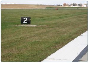
Runway Designation Marking
Runway numbers and letters are determined from the approach direction. The runway number is the whole number nearest one-tenth the magnetic azimuth of the centerline of the runway, measured clockwise from the magnetic north. In the case where there are parallel runways, the letters differentiate between left (L), right (R), or center (C). For example, if there are two parallel runways, they would show the designation number and then either L or R beneath it. For three parallel runways, the designation number would be presented with L, C, or R beneath it.
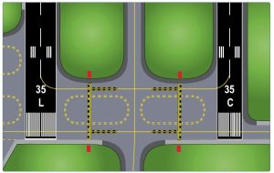
Figure 14-20A and B shows an example of a direction sign at a complex taxiway intersection. Figures below shows Taxiway Bravo intersects with Taxiway Sierra at 90°, but at 45° with Taxiway Foxtrot. This type of array can be displayed with or without the taxiway location sign, which in this case would be Taxiway Bravo.
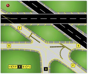
Taxiway Markings and Signs
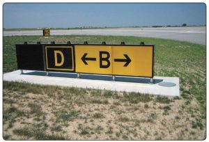
Taxiway direction signs have a yellow background and black characters, which identifies the designation or intersecting taxiways. Arrows indicate the direction of turn that would place the aircraft on the designated taxiway. Direction signs are normally located on the left side of the taxiway and prior to the intersection. These signs and markings (with a yellow background and black characters) indicate the direction toward a different taxiway, leading off a runway, or out of an intersection. Figure below shows Taxiway Delta and how Taxiway Bravo intersects ahead at 90° both left and right.
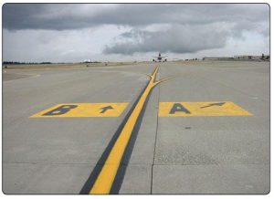
Taxiway direction signs can also be displayed as surface painted markings. Figure below shows Taxiway Bravo as proceeding straight ahead while Taxiway Alpha turns to the right at approximately 45°.
Destination Signs
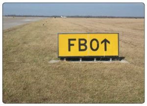
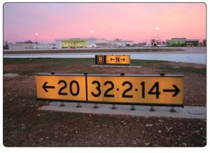
Destination signs have black characters on a yellow background indicating a destination at the airport. These signs always have an arrow showing the direction of the taxi route to that destination. When the arrow on the destination sign indicates a turn, the sign is located prior to the intersection. Destinations commonly shown on these types of signs include runways, aprons, terminals, military areas, civil aviation areas, cargo areas, international areas, and fixed-base operators. When the inscription for two or more destinations having a common taxi route are placed on a sign, the destinations are separated by a “dot” (•) and one arrow would be used as shown below. When the inscription on a sign contains two or more destinations having different taxi routes, each destination is accompanied by an arrow and separated from the other destination(s) on the sign with a vertical black message divider as shown. The example shown in figures below shows two signs. The sign in the foreground explains that Runway 20 threshold is to the left, and Runways 32, 2, and 14 are to the right. The sign in the background indicates that you are located on Taxiway Bravo and Taxiway November will take you to those runways.
Airport Signs
There are six types of signs that may be found at airports. The more complex the layout of an airport, the more important the signs become to pilots. Appendix C of this publication shows examples of some signs that are found at most airports, their purpose, and appropriate pilot action. The six types of signs are:
• Mandatory instruction signs—red background with white inscription. These signs denote an entrance to a runway, critical area, or prohibited area.
• Location signs—black with yellow inscription and a yellow border, no arrows. They are used to identify a taxiway or runway location, to identify the boundary of the runway, or identify an instrument landing system (ILS) critical area.
• Direction signs—yellow background with black inscription. The inscription identifies the designation of the intersecting taxiway(s) leading out of an intersection.
• Destination signs—yellow background with black inscription and arrows. These signs provide information on locating areas, such as runways, terminals, cargo areas, and civil aviation areas.
• Information signs—yellow background with black inscription. These signs are used to provide the pilot with information on areas that cannot be seen from the control tower, applicable radio frequencies, and noise abatement procedures. The airport operator determines the need, size, and location of these signs.
• Runway distance remaining signs—black background with white numbers. The numbers indicate the distance of the remaining runway in thousands of feet.
UA.V.B.K4 Traffic patterns used by manned aircraft pilots (AIM 4-3-2)
Airports with an Operating Control Tower (AIM 4-3-2, 3, & 4)
When operating at an airport where traffic control is being exercised by a control tower, pilots are required to maintain two-way radio contact with the tower while operating within the Class B, Class C, and Class D surface area unless the tower authorizes otherwise. Initial callup should be made about 15 miles from the airport. Unless there is a good reason to leave the tower frequency before exiting the Class B, Class C, and Class D surface areas, it is a good operating practice to remain on the tower frequency for the purpose of receiving traffic information. In the interest of reducing tower frequency congestion, pilots are reminded that it is not necessary to request permission to leave the tower frequency once outside of Class B, Class C, and Class D surface areas. Not all airports with an operating control tower will have Class D airspace. These airports do not have weather reporting which is a requirement for surface based controlled airspace, previously known as a control zone. The controlled airspace over these airports will normally begin at 700 feet or 1,200 feet above ground level and can be determined from the visual aeronautical charts. Pilots are expected to use good operating practices and communicate with the control tower as described in this section.
When necessary, the tower controller will issue clearances or other information for aircraft to generally follow the desired flight path (traffic patterns) when flying in Class B, Class C, and Class D surface areas and the proper taxi routes when operating on the ground. If not otherwise authorized or directed by the tower, pilots of fixed-wing aircraft approaching to land must circle the airport to the left. Pilots approaching to land in a helicopter must avoid the flow of fixed-wing traffic. However, in all instances, an appropriate clearance must be received from the tower before landing.
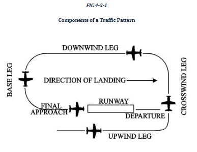
NOTE-
This diagram is intended only to illustrate terminology used in identifying various components of a traffic pattern. It should not be used as a reference or guide on how to enter a traffic pattern.
The following terminology for the various components of a traffic pattern has been adopted as standard for use by control towers and pilots:
-
- Upwind leg. A flight path parallel to the landing runway in the direction of landing.
- Crosswind leg. A flight path at right angles to the landing runway off its takeoff end.
- Downwind leg. A flight path parallel to the landing runway in the opposite direction of landing.
- Base leg. A flight path at right angles to the landing runway off its approach end and extending from the downwind leg to the intersection of the extended runway centerline.
- Final approach. A flight path in the direction of landing along the extended runway centerline from the base leg to the runway.
- Departure. The flight path which begins after takeoff and continues straight ahead along the extended runway centerline. The departure climb continues until reaching a point at least 1/2 mile beyond the departure end of the runway and within 300 feet of the traffic pattern altitude.
Many towers are equipped with a tower radar display. The radar uses are intended to enhance the effectiveness and efficiency of the local control, or tower, position. They are not intended to provide radar services or benefits to pilots except as they may accrue through a more efficient tower operation. The four basic uses are:
-
- To determine an aircraft’s exact location. This is accomplished by radar identifying the VFR aircraft through any of the techniques available to a radar position, such as having the aircraft squawk ident. Once identified, the aircraft’s position and spatial relationship to other aircraft can be quickly determined, and standard instructions regarding VFR operation in Class B, Class C, and Class D surface areas will be issued. Once initial radar identification of a VFR aircraft has been established and the appropriate instructions have been issued, radar monitoring may be discontinued; the reason being that the local controller’s primary means of surveillance in VFR conditions is visually scanning the airport and local area.
- To provide radar traffic advisories. Radar traffic advisories may be provided to the extent that the local controller is able to monitor the radar display. Local control has primary control responsibilities to the aircraft operating on the runways, which will normally supersede radar monitoring duties.
- To provide a direction or suggested heading. The local controller may provide pilots flying VFR with generalized instructions which will facilitate operations; e.g., “PROCEED SOUTHWESTBOUND, ENTER A RIGHT DOWNWIND RUNWAY THREE ZERO,” or provide a suggested heading to establish radar identification or as an advisory aid to navigation; e.g., “SUGGESTED HEADING TWO TWO ZERO, FOR RADAR IDENTIFICATION.” In both cases, the instructions are advisory aids to the pilot flying VFR and are not radar vectors.
NOTE-
Pilots have complete discretion regarding acceptance of the suggested headings or directions and have sole responsibility for seeing and avoiding other aircraft.
- To provide information and instructions to aircraft operating within Class B, Class C, and Class D surface areas. In an example of this situation, the local controller would use the radar to advise a pilot on an extended downwind when to turn base leg.
NOTE-
The above tower radar applications are intended to augment the standard functions of the local control position. There is no controller requirement to maintain constant radar identification. In fact, such a requirement could compromise the local controller’s ability to visually scan the airport and local area to meet FAA responsibilities to the aircraft operating on the runways and within the Class B, Class C, and Class D surface areas. Normally, pilots will not be advised of being in radar contact since that continued status cannot be guaranteed and since the purpose of the radar identification is not to establish a link for the provision of radar services.
A few of the radar equipped towers are authorized to use the radar to ensure separation between aircraft in specific situations, while still others may function as limited radar approach controls. The various radar uses are strictly a function of FAA operational need. The facilities may be indistinguishable to pilots since they are all referred to as tower and no publication lists the degree of radar use. Therefore, when in communication with a tower controller who may have radar available, do not assume that constant radar monitoring and complete ATC radar services are being provided.
Traffic Patterns (AIM 4-3-3)
It is recommended that aircraft enter the airport traffic pattern at one of the following altitudes listed below. These altitudes should be maintained unless another traffic pattern altitude is published in the Chart Supplement or unless otherwise required by the applicable distance from cloud criteria (14 CFR Section 91.155):
-
- Propeller-driven aircraft enter the traffic pattern at 1,000 feet above ground level (AGL).
- Large and turbine-powered aircraft enter the traffic pattern at an altitude of not less than 1,500 feet AGL or 500 feet above the established pattern altitude.
- Helicopters operating in the traffic pattern may fly a pattern similar to the fixed-wing aircraft pattern, but at a lower altitude (500 AGL) and closer to the runway. This pattern may be on the opposite side of the runway from fixed-wing traffic when airspeed requires or for practice power-off landings (autorotation) and if local policy permits. Landings not to the runway must avoid the flow of fixed wing traffic.
A pilot may vary the size of the traffic pattern depending on the aircraft’s performance characteristics. Pilots of en route aircraft should be constantly alert for aircraft in traffic patterns and avoid these areas whenever possible.
- Unless otherwise indicated, all turns in the traffic pattern must be made to the left, except for helicopters, as applicable.
- On Sectional, Aeronautical, and VFR Terminal Area Charts, right traffic patterns are indicated at public-use and joint-use airports with the abbreviation “RP” (for Right Pattern), followed by the appropriate runway number(s) at the bottom of the airport data block.
EXAMPLE-
RP 9, 18, 22R
NOTE-
- Pilots are encouraged to use the standard traffic pattern. However, those pilots who choose to execute a straight-in approach, maneuvering for and execution of the approach should not disrupt the flow of arriving and departing traffic. Likewise, pilots operating in the traffic pattern should be alert at all times for aircraft executing straight-in approaches.
REFERENCE-
AC 90-66B, Non-Towered Airport Flight Operations.
- *RP indicates special conditions exist and refers pilots to the Chart Supplement.
- Right traffic patterns are not shown at airports with full-time control towers.
Wind conditions affect all airplanes in varying degrees. Below is an example of a chart used to determine the headwind, crosswind, and tailwind components based on wind direction and velocity relative to the runway. Pilots should refer to similar information provided by the aircraft manufacturer when determining these wind components.
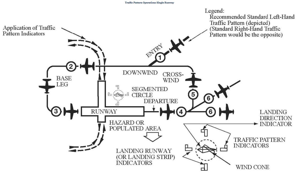
Visual Indicators at Airports Without an Operating Control Tower (AIM 4-3-4)
At those airports without an operating control tower, a segmented circle visual indicator system, if installed, is designed to provide traffic pattern information.
REFERENCE-
AIM, Para 4-1-9, Traffic Advisory Practices at Airports Without Operating Control Towers.
The segmented circle system consists of the following components:
-
- The segmented circle. Located in a position affording maximum visibility to pilots in the air and on the ground and providing a centralized location for other elements of the system.
- The wind direction indicator. A wind cone, wind sock, or wind tee installed near the operational runway to indicate wind direction. The large end of the wind cone/wind sock points into the wind as does the large end (cross bar) of the wind tee. In lieu of a tetrahedron and where a wind sock or wind cone is collocated with a wind tee, the wind tee may be manually aligned with the runway in use to indicate landing direction. These signaling devices may be located in the center of the segmented circle and may be lighted for night use. Pilots are cautioned against using a tetrahedron to indicate wind direction.
- The landing direction indicator. A tetrahedron is installed when conditions at the airport warrant its use. It may be used to indicate the direction of landings and takeoffs. A tetrahedron may be located at the center of a segmented circle and may be lighted for night operations. The small end of the tetrahedron points in the direction of landing. Pilots are cautioned against using a tetrahedron for any purpose other than as an indicator of landing direction. Further, pilots should use extreme caution when making runway selection by use of a tetrahedron in very light or calm wind conditions as the tetrahedron may not be aligned with the designated calm-wind runway. At airports with control towers, the tetrahedron should only be referenced when the control tower is not in operation. Tower instructions supersede tetrahedron indications.
- Landing strip indicators. Installed in pairs as shown in the segmented circle diagram and used to show the alignment of landing strips.
- Traffic pattern indicators. Arranged in pairs in conjunction with landing strip indicators and used to indicate the direction of turns when there is a variation from the normal left traffic pattern. (If there is no segmented circle installed at the airport, traffic pattern indicators may be installed on or near the end of the runway.)
Preparatory to landing at an airport without a control tower, or when the control tower is not in operation, pilots should concern themselves with the indicator for the approach end of the runway to be used. When approaching for landing, all turns must be made to the left unless a traffic pattern indicator indicates that turns should be made to the right. If the pilot will mentally enlarge the indicator for the runway to be used, the base and final approach legs of the traffic pattern to be flown immediately become apparent. Similar treatment of the indicator at the departure end of the runway will clearly indicate the direction of turn after takeoff.
When two or more aircraft are approaching an airport for the purpose of landing, the pilot of the aircraft at the lower altitude has the right-of-way over the pilot of the aircraft at the higher altitude. However, the pilot operating at the lower altitude should not take advantage of another aircraft, which is on final approach to land, by cutting in front of, or overtaking that aircraft.
UA.V.B.K5 Security Identification Display Areas (SIDA)(Part 153 Airport Operations)
Security Identification Display Area (SIDA) means a portion of an airport, specified in the airport security program, in which security measures specified in Title 49 of the Code of Federal Regulations are carried out. This area includes the secured area and may include other areas of the airport.
UA.V.B.K6 Sources for airport data (FAA-H-8083-25 pg. 14-3)
When a pilot flies into a different airport, it is important to review the current data for that airport. This data provides the pilot with information, such as communication frequencies, services available, closed runways, or airport construction. Three common sources of information are:
• Aeronautical Charts
• Chart Supplement U.S. (formerly Airport/Facility Directory)
• Notices to Airmen (NOTAMs)
• Automated Terminal Information Service (ATIS)
UA.V.B.K6a Aeronautical charts (FAA-H-8083-25 pg. 16-2)
An aeronautical chart is the road map for a pilot flying under VFR. The chart provides information that allows pilots to track their position and provides available information that enhances safety. The three aeronautical charts used by VFR pilots are:
• Sectional
• VFR Terminal Area
• World Aeronautical
A free catalog listing aeronautical charts and related publications including prices and instructions for ordering is available at the Aeronautical Navigation Products website: www.aeronav.faa.gov.
Sectional Charts
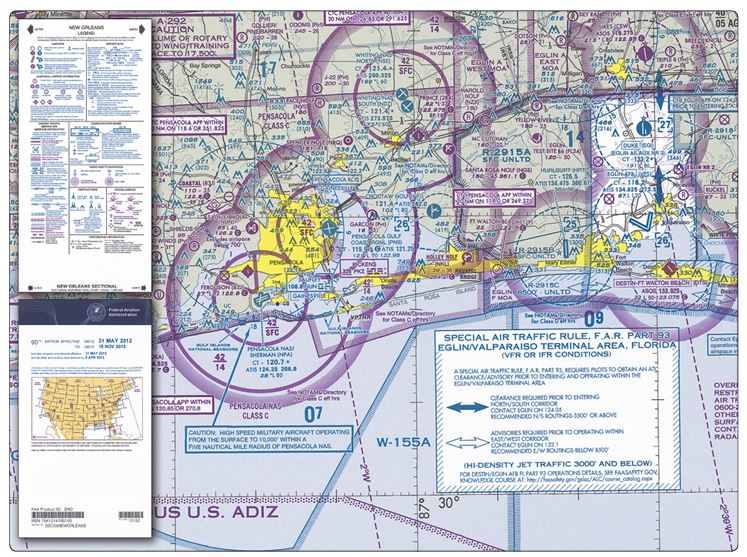
Sectional charts are the most common charts used by pilots today. The charts have a scale of 1:500,000 (1 inch = 6.86 nautical miles (NM) or approximately 8 statute miles (SM)), which allows for more detailed information to be included on the chart.
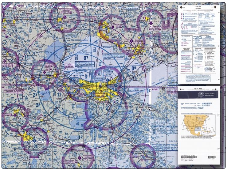
The charts provide an abundance of information, including airport data, navigational aids, airspace, and topography. Below is an excerpt from the legend of a sectional chart. By referring to the chart legend, a pilot can interpret most of the information on the chart. A pilot should also check the chart for other legend information, which includes air traffic control (ATC) frequencies and information on airspace. These charts are revised semiannually except for some areas outside the conterminous United States where they are revised annually.
VFR Terminal Area Charts
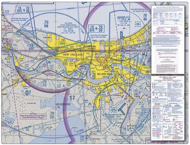
VFR terminal area charts are helpful when flying in or near Class B airspace. They have a scale of 1:250,000 (1 inch = 3.43 NM or approximately 4 SM). These charts provide a more detailed display of topographical information and are revised semiannually, except for several Alaskan and Caribbean charts.
World Aeronautical Charts
World aeronautical charts are designed to provide a standard series of aeronautical charts, covering land areas of the world, at a size and scale convenient for navigation by moderate speed aircraft. They are produced at a scale of 1:1,000,000 (1 inch = 13.7 NM or approximately 16 SM). These charts are similar to sectional charts, and the symbols are the same except there is less detail due to the smaller scale. [Figure 16-3] These charts are revised annually except several Alaskan charts and the Mexican/Caribbean charts, which are revised every 2 years.
Latitude and Longitude (Meridians and Parallels)
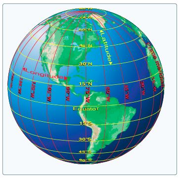
The equator is an imaginary circle equidistant from the poles of the Earth. Circles parallel to the equator (lines running east and west) are parallels of latitude. They are used to measure degrees of latitude north (N) or south (S) of the equator. The angular distance from the equator to the pole is one-fourth of a circle or 90°. The 48 conterminous states of the United States are located between 25° and 49° N latitude. The arrows in the figure below labeled “Latitude” point to lines of latitude. Meridians of longitude are drawn from the North Pole to the South Pole and are at right angles to the Equator. The “Prime Meridian,” which passes through Greenwich, England, is used as the zero line from which measurements are made in degrees east (E) and west (W) to 180°. The 48 conterminous states of the United States are between 67° and 125° W longitude.
Any specific geographical point can be located by reference to its longitude and latitude. Washington, D.C., for example, is approximately 39° N latitude, 77° W longitude. Chicago is approximately 42° N latitude, 88° W longitude.
UA.V.B.K6b Chart Supplements (FAA-H-8083-25 pg. 14-4)
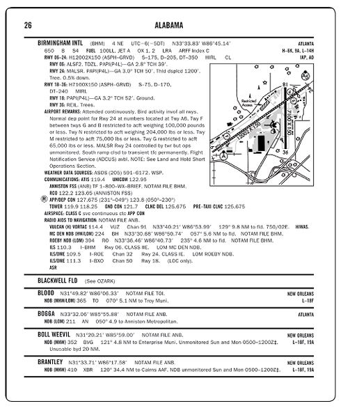
The Chart Supplement U.S. (formerly Airport/Facility Directory) provides the most comprehensive information on a given airport. It contains information on airports, heliports, and seaplane bases that are open to the public. The Chart Supplement U.S. is published in seven books, which are organized by regions and are revised every 56 days. The Chart Supplement U.S. is also available digitally at www.faa.gov/air_traffic/flight_info/aeronav. Figure below contains an excerpt from a directory. For a complete listing of information provided in a Chart Supplement U.S. and how the information may be decoded, refer to the “Legend Sample” located in the front of each Chart Supplement U.S.
In addition to airport information, each Chart Supplement U.S. contains information such as special notices, Federal Aviation Administration (FAA) and National Weather Service (NWS) telephone numbers, preferred instrument flight rules (IFR) routing, visual flight rules (VFR) waypoints, a listing of very high frequency (VHF) omnidirectional range (VOR) receiver checkpoints, aeronautical chart bulletins, land and hold short operations (LAHSO) for selected airports, airport diagrams for selected towered airports, en route flight advisory service (EFAS) outlets, parachute jumping areas, and facility telephone numbers. It is beneficial to review a Chart Supplement U.S. to become familiar with the information it contains.
UA.V.B.K7 Avoiding bird and wildlife hazards and reporting collisions between aircraft and wildlife (AC 150/5200-32B)
The FAA has long recognized the threat to aviation safety posed by wildlife strikes. Each year in the United States, wildlife strikes to U.S. civil aircraft cause about $718 million in damage to aircraft and about 567,000 hours of civil aircraft down time. For the period 1990 to 2011, over 115,000 wildlife strikes were reported to the FAA. About 97 percent of all wildlife strikes reported to the FAA involved birds, about 2 percent involved terrestrial mammals, and less than 1 percent involved flying mammals (bats) and reptiles. Waterfowl (ducks and geese), gulls, and raptors (mainly hawks and vultures) are the bird species that cause the most damage to civil aircraft in the United States, while European starlings are responsible for the greatest loss of human life. Vultures and waterfowl cause the most losses to U.S. military aircraft.
Studies have shown that strike reporting has steadily increased over the past two decades; however, strike reporting is not consistent across all stakeholders (pilots, air carriers, airport operators, air traffic control personnel, etc.) in the National Airspace System. Although larger 14 CFR Part 139 airports and those with well-established wildlife programs have improved strike reporting, there is a wide disparity in overall reporting rates between Part 139 airports and general aviation (GA) airports in the National Plan of Integrated Airport Systems (NPIAS). Less than 6 percent of total strike reports come from NPIAS GA airports, whose reporting rates average less than 1/20th the rates at Part 139 airports. Most Part 139 airports (97 percent) have reported at least one strike into the database through 2011, while only 43 percent of NPIAS GA airports have documented a strike into the database.
UA.V.B.K8 Airport and seaplane base lighting (FAA-H-8083-25)
The majority of airports have some type of lighting for night operations. The variety and type of lighting systems depends on the volume and complexity of operations at a given airport. Airport lighting is standardized so that airports use the same light colors for runways and taxiways.
Airport Beacon
Airport beacons help a pilot identify an airport at night. The beacons are normally operated from dusk until dawn. Sometimes they are turned on if the ceiling is less than 1,000 feet and/or the ground visibility is less than 3 statute miles (VFR minimums). However, there is no requirement for this, so a pilot has the responsibility of determining if the weather meets VFR requirements. The beacon has a vertical light distribution to make it most effective from 1–10° above the horizon, although it can be seen well above or below this spread. The beacon may be an omnidirectional capacitor-discharge device, or it may rotate at a constant speed, that produces the visual effect of flashes at regular intervals. The combination of light colors from an airport beacon indicates the type of airport. Some of the most common beacons are:
• Flashing white and green for civilian land airports
• Flashing white and yellow for a water airport
• Flashing white, yellow, and green for a heliport
• Two quick white flashes alternating with a green flash identifying a military airport
![]()
Runway Lighting
There are various lights that identify parts of the runway complex. These assist a pilot in safely making a takeoff or landing during night operations.
Runway End Identifier Lights (REIL)
Runway end identifier lights (REIL) are installed at many airfields to provide rapid and positive identification of the approach end of a particular runway. The system consists of a pair of synchronized flashing lights located laterally on each side of the runway threshold. REILs may be either omnidirectional or unidirectional facing the approach area.
Runway Edge Lights
Runway edge lights are used to outline the edges of runways at night or during low visibility conditions. These lights are classified according to the intensity they are capable of producing: high intensity runway lights (HIRL), medium intensity runway lights (MIRL), and low intensity runway lights (LIRL). The HIRL and MIRL have variable intensity settings. These lights are white, except on instrument runways where amber lights are used on the last 2,000 feet or half the length of the runway, whichever is less. The lights marking the end of the runway are red.
Control of Airport Lighting
Airport lighting is controlled by ATC at towered airports. At nontowered airports, the lights may be on a timer, or where an FSS is located at an airport, the FSS personnel may control the lighting. A pilot may request various light systems be turned on or off and also request a specified intensity, if available, from ATC or FSS personnel. At selected nontowered airports, the pilot may control the lighting by using the radio. This is done by selecting a specified frequency and clicking the radio microphone. For information on pilot controlled lighting at various airports, refer to the Chart Supplement U.S. (formerly Airport/Facility Directory).
Taxiway Lights
Similar to runway lighting, taxiways also have various lights which help pilots identify areas of the taxiway and any surrounding runways.
Omnidirectional
Omnidirectional taxiway lights outline the edges of the taxiway and are blue in color. At many airports, these edge lights may have variable intensity settings that may be adjusted by an ATC when deemed necessary or when requested by the pilot. Some airports also have taxiway centerline lights that are green in color. Clearance Bar Lights Clearance bar lights are installed at holding positions on taxiways in order to increase the conspicuity of the holding position in low visibility conditions. They may also be installed to indicate the location of an intersecting taxiway during periods of darkness. Clearance bars consist of three in-pavement steady-burning yellow lights.
Runway Guard Lights
Runway guard lights are installed at taxiway/runway intersections. They are primarily used to enhance the conspicuity of taxiway/runway intersections during low visibility conditions, but may be used in all weather conditions. Runway guard lights consist of either a pair of elevated flashing yellow lights installed on either side of the taxiway, or a row of in-pavement yellow lights installed across the entire taxiway, at the runway holding position marking.
Note: Some airports may have a row of three or five in-pavement yellow lights installed at taxiway/runway intersections. They should not be confused with clearance bar lights described previously in this section. Stop Bar Lights Stop bar lights, when installed, are used to confirm the ATC clearance to enter or cross the active runway in low visibility conditions (below 1,200 ft Runway Visual Range (RVR)). A stop bar consists of a row of red, unidirectional, steady burning in-pavement lights installed across the entire taxiway at the runway holding position, and elevated steady-burning Obstruction Lights Obstructions are marked or lighted to warn pilots of their presence during daytime and nighttime conditions. Obstruction lighting can be found both on and off an airport to identify obstructions. They may be marked or lighted in any of the following conditions. • Red obstruction lights—flash or emit a steady red color during nighttime operations, and the obstructions are painted orange and white for daytime operations. • High intensity white obstruction lights—flash high intensity white lights during the daytime with the intensity reduced for nighttime. • Dual lighting—a combination of flashing red beacons and steady red lights for nighttime operation and high intensity white lights for daytime operations.

